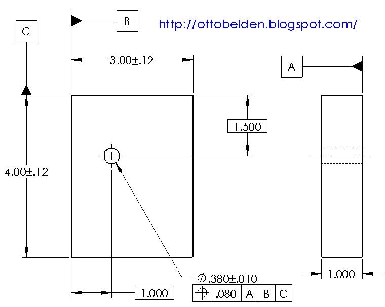

Why are we trying to hit that area? Perhaps because we want a round pin to fit in a round hole. Using a circular tolerance zone instead of a square one also makes more sense if you think about it.
#TRUE POSITION ONE DATUM PLUS#
Look at it this way–the 4 areas of the True Position Tolerance Zone that are outside the plus minus tolerance zone make it clear that there are places where one of the two plus/minus tolerenaces could be broken and the feature would still be within tolerance! In fact, it is quite a bit less.īecause we are allowed to hit a larger position deviation with GD&T’s True Position concept, it’s easier. If we can only use plus/minus tolerancing, all we can do is use the square, which is forcing us to a smaller area in which our actual hole center must fit: the area of the yellow square is certainly less than the red circle. Now you may have heard people say that GD&T actually lets us use looser tolerances so parts are cheaper to make. You only have a little more than a third of True Position in each dimension for your plus/minus tolerance.


It’s sides in this case are 0.71″ (at this precision, it’s actually the square root of 0.5, the circle’s radius), so we’d use plus or minus half that to get a position deviation of plus or minus 0.355. If we were using traditional plus/minus tolerancing, we would use something along the lines of the yellow square. Traditional plus/minus tolerancing must fit inside the yellow square… Now let’s relate that True Position back to convention plus/minus or limit dimensions. So the True Position in this example would be 0.7071, which is within the 1.00 position deviation called out for the True Position–we’re okay! The actual position of our hole differs from True Position by 0.25 in both X and Y. The True Position is 1.00 (keeping it in round numbers to make it easier to scale your real numbers and see what all this means). In this example, the Red Circle is the tolerance zone for the hole center. The Red Circle is the tolerance zone for the hole center… Since a picture is worth a thousand words, geometrically, what we’ve been talking about looks like this: True Position can be tougher than it looks on first glance! We’re off from the 0.0015 True Position maximum allowed positional deviation by almost 2x!Įven with half the differences, so X and Y are within 0.00075″ of the true center, the True Position still works out to be 0.002121″. That gives us the following True Position Formula: Let’s say we’re off by 0.0015 in both X and Y. So, we take the difference in X (difference between actual and measured X), square it, add that to the difference in Y squared, take the square root of that sum and multiply by 2. True Position = 2 x SQRT(XVAR^2 + YVAR^2) Here’s the usual True Position Formula for X and Y:
#TRUE POSITION ONE DATUM HOW TO#
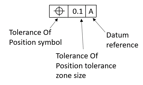
But is that really true? To understand the answer, we must understand how to calculate true position: How to Calculate True Position Many who are not familiar with GD&T True Position may jump to the conclusion that they just need to locate within a thou and a half (0.0015″) on X and Y and all will be well. So how far off can the center actually be? Let’s say the callout gives a true position tolerance of 0.0015″. Consider the true position of the center of a hole, a very common application. Depending on how it is called out, true position can be used in a lot of different ways. True Position is the total permissible position deviation that a feature can have from its “true” or theoretical position–that is, the total variation from the actual position if there was no error on an ideal part. True Positions are relative to Datums, so you will want to spell out which datums in the Feature Control Block are associated with a True Position. The GD&T Symbol for True Position is a little crosshairs: There are two forms of GD&T True Position–one for a feature size under a material condition (Maximum Material Condition or Least Material Condition), and one for True Position Regardless of Feature Size (RFS). GD&T uses a notion called True Position when tolerancing locations. Now let’s put all of that together by taking our first look at the GD&T concepts around tolerancing positions or locations and let’s also take a look at the true position formula and using a true position calculator. We just finished going over plus/minus tolerancing–the way most drawings that don’t use GD&T are toleranced. You know how Datums and Feature Control Blocks work, for example.

We’ve picked up a lot of fundamentals in prior chapters.


 0 kommentar(er)
